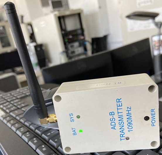
Figure 1 front view of the transmitter
1、 Power on
Press the power button to start the machine
2、 Parameter configuration
Before using the transmitter for the first time, it is recommended to modify the working parameters.The details are as follows:
(1) Default parameters:
const Aircraft_ParaST default_init_param={
0x780000, / / ICAO address, 01 command setting
"Test1234", / / flight number, 40 command setting
1, //Aircraft type, 04 command setting, 1: light
0xe00, / / secondary radar code, 02 command setting
5 //Ground speed, 03 command set 65knots = 120km / h, 10km / h = 5knots
};
(2) When modifying the parameters, it is necessary to use the usb-c interface cable to connect with the computer and install the driver cp210x_Universal_Windows_Driver. Zip (or ch341ser. Exe), and then download the serial debugging assistant serial_port_utility_To open the serial port debugging assistant software, the interface is as follows (baud rate 115200bps, port number of different computers is different, here is com9).
Figure 2 display interface of serial port debugging assistant
(3) To use hexadecimal sending mode: select the "hex" option in "sending settings";
(4) Input the following command as required (4 bytes or 9 words, command format: command word (1 byte) + command content (3 or 8 bytes)), and then click the "send" button to change the required parameters.
01Set 24bit ICAO address: 01 xx1 XX2 XX3, for example: 01 12 34 56, set local ICAO address as 0x123456
02Set 10bit SSR Code: 02 xx1 XX2 00, where xx1 XX2 is the hexadecimal number of SSR code
For example: 020e 00 00 8 base 7000 = 0xe00 (16 base)
03Set VSO (ground speed): 03 xx1 XX2 00, where xx1 XX2 is a hexadecimal number
For example: 03 00 05 00, set the ground speed to 5 knots, that is, the speed message will be sent only when it is higher than the speed
04Set aircraft model: 04 XX 00
For example: 04 01 00, set to light aircraft
1: light (< 15500 lbs.);
2: small (15500 to 75000 lbs.);
3: large (75000 to 300000 lbs.);
4: high whirlpool type large aircraft (such as b-757 aircraft);
5: heavy (> 300000 lbs.);
6: high performance;
7: rotorcraft;
40Set the flight number: 40 C1 ~ C8. If you set the flight number as "test0123", the corresponding command is (string): @ test0123. Note: the flight number can only be capital letters (a ~ z) or numbers (0 ~ 9);
Note: 01-04 and 40 only modify the flight parameters, but they are not stored in EEPROM. Therefore, when the system is restarted, the modified parameters will change to the values before modification;To work when the system restarts later, you must call the 05 command to save the parameters after modifying the parameters.
05 00 00 00Save parameters: write the modified parameters to EEPROM
06 00 00 00Restore default parameters: restore the default parameters and write them to EEPROM
07 00 00 00 Display current working parameters
08 XX 00 00 set and save the current air pressure altitude, XX is a hexadecimal number, using 2 complement, unit: m, range: - 128 ~ 127m, namely 80 ~ 7F
(5) Serial port output test information description
Output 1 message per second, as follows:
00:00:44 spd=0 dir=2346 vdop=86 st=10,4/14, MS=-1515,2727,H=1130/2450,Volt=396 /1387, 390997783,1173496283
Specific meaning:
00:00:44: working hours
SPD = 0: speed (0.1 knots)
Dir = 2346: direction (0.01 degrees), 1.99 degrees (the direction is meaningless when SPD = 0)
vdop=86:vdop(0.01) ,0.86
St = 00: status (B0: IIC error, B1: PLL error, B2: GPS not locked, B3: 14V RF voltage too low, B4: GPS altitude)
4/14: messages per second / 10 seconds: 4 messages per second, 14 messages per 10 seconds (1.4 messages per second on average)
Ms = - 15152727: absolute pressure height (0.01M): - 15.15m;Temperature (0.01)°C) : 27.27°C
H = 1130 / 2450: compensated barometric height / GPS height (0.01M), barometric height 11.3m, GPS height 24.5m (if vdop value is less than 1.3 for 10 seconds, the barometric height will be automatically corrected by GPS height)
Volt = 396 / 1387 battery / RF power amplifier MOS supply voltage (0.01V), 3.95V, 13.87v
390997783,1173496283: current latitude, longitude
3、 Power off: when power on, press the "power" button (the status LED turns red) for more than 2 seconds. When the status LED turns blue, release the button to complete the power off;In addition, when the battery voltage is less than 5% (3.45v), it will turn off automatically (the red LED will turn blue after 2 seconds, and then turn off automatically).
4、 Description of LED indicator
Description of LED indicator light:
Power LED:
Green flashing (1Hz): more than 60% power
Orange flashing (1Hz): more than 30% power
Red flashing (1Hz): less than 30% power
Flashing blue (1Hz): charging
System led:
Flashing blue: launching (in the air)
Flashing green: launching (GPS normal)
Red flashing: no GPS signal (only transmitting status message)
Flashing orange: PLL not locked or IIC error
Charging LED (when usb-c is connected to computer or charging head)
Green on: charging
Green off: charging complete
5、 Charging
Connect the transmitter with the USB interface of the computer or other + 5V power adapter by using the usb-c interface cable to charge the transmitter. When charging, the green charging indicator lights up and goes out after charging;While charging, the transmitter can also work, at this time, the battery "bat" LED flashes blue;The green LED flashes after charging.
6、 Main working parameters
(1) Charging Voltage 5V, 500mA, interface: USB-type C
(2) ADS-B antenna interface, SMA outer screw inner hole
(3) Size (mm): 115 * 58 * 34
(4) Transmitting power: not less than 25dbm
(5) Weight: less than 200g
(6) Working time after full charge: no less than 6 hours
